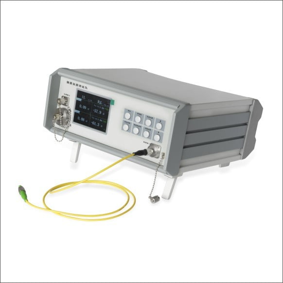
Insertion loss & Return loss tester patch cord and pigtail PLC8T
Insertion loss & Return loss tester patch cord and pigtail PLC8T is a précised fiber optical tested designed by us based on their own production experiences and customer requirements. It is widely used for testing of insertion and return loss of fiber optical passive components and fiber telecom industry. It is a basic and ideal tester for factories, research institutions and operating companies.
It has a unique insertion loss data warning set. Different color shows. Testing efficiency is enhanced greatly. Operating is easy and electrical circuit design is superb. It saves operating steps for large active scale and micro signals detecting. Its unique designed joint can be dismounted. Power meter interface is also available.
What Is Insertion Loss?
In telecommunications, insertion loss refers to the loss of signal power, calculated as a ratio in dB (decibel), resulting from inserting a device in a transmission line or optical fiber. It can also be referred to as attenuation, which indicates how much the signal loss is by comparing the input power to the output power. A lower insertion loss value indicates a better insertion loss performance. For example, an insertion loss of 0.3dB is better than 0.5dB.
What Is Return Loss?
When a signal is transmitted through a transmission line, some signal power is always reflected or returned to the source due to discontinuities in the transmission line. The discontinuity can be a mismatch with the terminating load or with a device inserted in the line. Return loss refers to the loss of reflected signal power. Therefore, the higher the return loss is, the lower the amount of reflection will be. That is to say, the fiber connector will have better performance with a higher value of RL.
What Causes Poor Insertion Loss and Return Loss?
Ideally speaking, if the fiber patch cable has no connections, then the minimum loss will be realized—a continuous, straight-through glass fiber from Point A to Point B with no interruptions. However, the fiber optic networks are requiring connectors for modularity. The desired low IL and high RL performance are reduced consequently on account of the following three factors:
End-face Quality and Cleanliness

Evidently, fiber end-face defects like scratches, pits, cracks, and particle contamination will have a direct impact on the performance, contributing to poor insertion/return loss. Any irregularity that impedes light transmission from one fiber to the other will negatively affect IL and RL.
Misalignment Between the Two Cores
The main task of the connector is to hold the fibers precisely, ensuring the core of one fiber will align neatly and accurately with the core of the other fiber, so as to make every connector to mate with another connector with precise core alignment and core-to-core contact. Normally speaking, the smaller the ferrule hole diameter, the more precisely the fiber will be centered in the ferrule. If the ferrule hole is not perfectly centered, the fiber it holds will obviously never be perfectly centered. Therefore, the misalignment between two cores often happens when the fibers with the light-carrying cores are not aligned perfectly with each other, resulting in poor IL/RL.

Poor Core-to-core Contact
In order to achieve the desired low IL and high RL, optimized core-to-core contact must be achieved and maintained. Different polishing styles of fiber connectors have varied core-to-core contact performance regarding the connector’s insertion loss and return loss. Usually, the insertion loss of PC, UPC, and APC connectors is less than 0.3dB. However, UPC connectors have the lowest IL due to the smallest air gap while APC connectors have the highest RL due to the beveled fiber end-face. PC vs UPC vs APC Connector will help you to select the proper fiber connect type.


Reviews
There are no reviews yet.