

What Is QSFP28 100G LR4 4xLWDM 10km Transceiver Module?
QSFP28 100G LR4 4xLWDM 10km Transceiver Module CISCO, HUAWEI, H3C, Juniper, D-link, HP, IBM, dell, Mikrotik, Aruba,Quidway Compatible This product is a 100Gb/s transceiver module designed for optical communication applications compliant to 100GBASE-LR4 of the IEEE P802.3ba standard. The module converts 4 input channels of 25Gb/s electrical data to 4 channels of LAN WDM optical signals and then multiplexes them into a single channel for 100Gb/s optical transmission. Reversely on the receiver side, the module de-multiplexes a 100Gb/s optical input into 4 channels of LAN WDM optical signals and then converts them to 4 output channels of electrical data. The central wavelengths of the 4 LAN WDM channels are 1295.56, 1300.05, 1304.58 and 1309.14 nm as members of the LAN WDM wavelength grid defined in IEEE 802.3ba. The high performance cooled LAN WDM DFB transmitters and high sensitivity PIN receivers provide superior performance for 100Gigabit Ethernet applications up to 10km links and compliant to optical interface with IEEE802.3ba Clause 88 100GBASE-LR4 requirements.
Product Features QSFP28 100G LR4 4xLWDM 10km Optical Transceiver
- Hot pluggable QSFP28 MSA form factor.
- Compliant to IEEE 802.3ba 100GBASE-LR4.
- Up to 10km reach for G.652 SMF.
- Single +3.3V power supply.
- Operating case temperature: 0~70℃.
- Transmitter: cooled 4x25Gb/s LAN WDM TOSA (1295.56, 1300.05, 1304.58, 1309.14nm).
- Receiver: 4x25Gb/s PIN ROSA.
- 4x28G Electrical Serial Interface (CEI-28G-VSR).
- Maximum power consumption 3.5W.
- Duplex LC receptacle.
- RoHS-6 compliant
Applications QSFP28 100G LR4 4xLWDM 10km Transceiver Module
- 100GBASE-LR4 Ethernet Links.
- Infiniband QDR and DDR interconnects.
- Client-side 100G Telecom connections
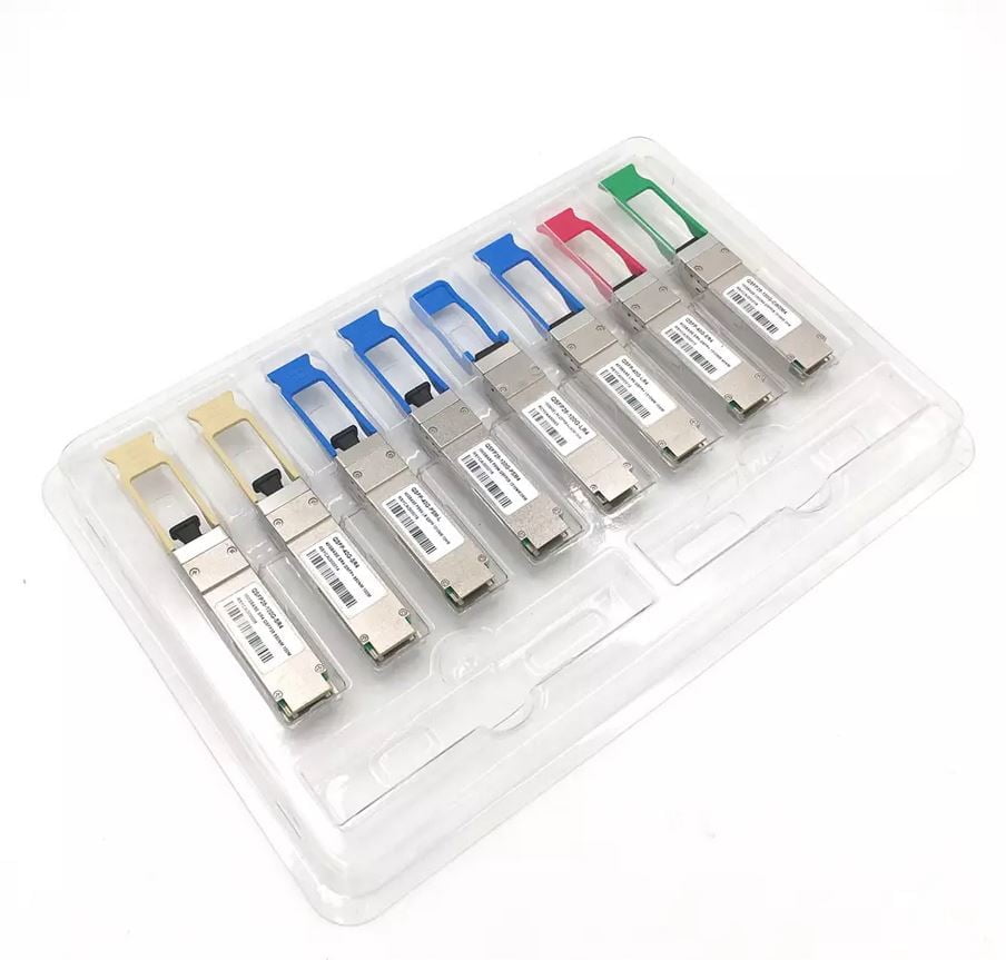
QSFP28 100G LR4 4xLWDM 10km Transceiver Module
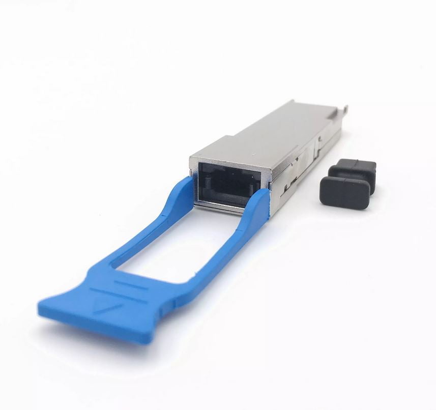
QSFP28 100G LR4 4xLWDM 10km Transceiver Module
What is an (Fiber) Optical Transceiver?
An Optical transceiver module is the core part of optical communication devices. It uses fiber optical technology to send and receive data through completing the process of optical signal – electrical signal / electrical signal – optical signal conversion. An optical transceiver module consists of two parts: the receiving part and the transmitting part. The receiving part realizes the photo-electric conversion, and the transmitting part realizes the electro-optical conversion.
Usually, one end of the transceiver will be connected to a cable and the opposite end of will have a special connector for fitting it into specific models of enterprise-grade Ethernet switches, routers or network interface cards
How to Classify Optical Transceivers?
In order to meet a variety of needs of transmission, the manufacturers launched a variety of categories of optical modules. Below are some common methods to classify them.
1)Sort by Rate
400GE optical transceiver module,
200GE optical transceiver module,
100GE optical transceiver module,
40GE optical transceiver module,
25GE optical transceiver module,
10GE optical transceiver module and etc.
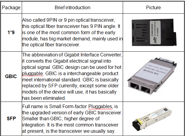
2)Sort by Package
The higher the transmission rate of the optical transceiver, the more complex the structure. In order to meet the needs of different structures, a variety of packaging types of optical transceiver modules were designed. For example, XFP, SFP, SFP+ for 10G transceivers, QSFP+ for 40G transceivers, CFP4, CFP2 and QSFP28 for 100G transceivers, as well as the latest OSFP and QSFP-DD for 400G transceivers.
- XFP (10GB Small Form-factor Pluggable) optical module: “X” is the abbreviation of Roman numerals 10, all XFP modules are 10G optical module. The XFP optical module supports LC fiber optic connectors and supports hot plugging. Compared to SFP+ and SFP optical modules, XFP optical modules are larger and longer.
- SFP (Small Form-factor Pluggable) optical module: smaller than XFP, SFP optical modules support LC fiber optic connectors, hot plugging.
- SFP+ (Small Form-factor Pluggable Plus) optical module: SFP+ refers to the increased rate of SFP module, sensitive to EMI.
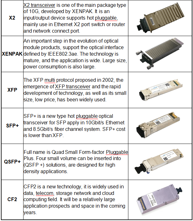
- QSFP+ (Quad Small Form-factor Pluggable Plus) optical module: four-channel small hot plugging optical module. The QSFP + optical module supports MPO fiber connectors, which are larger in size than SFP + optical modules.
- CFP (Centum Form-factor Pluggable) optical module: length × width × height of CFP is defined as 144.75mm × 82mm × 13.6mm, high-speed, hot plugging and supporting for data communications and telecommunications applications.
- QSFP28 optical module: the interface package size of QSFP28 is the same with QSFP+, which is mainly used in Data Center application.
- OSFP (Octal Small Form Factor Pluggable) optical module: the OSFP is a new pluggable form factor with eight high speed electrical lanes that will initially support 400 Gbps (8x50G). It is slightly wider and deeper than the QSFP but it still supports 32 OSFP ports per 1U front panel, enabling 12.8 Tbps per 1U.
- QSFP-DD (Quad Small Form Factor Pluggable Double Density) optical module: QSFP-DD is a new module and cage/connector system similar to current QSFP, but with an additional row of contacts providing for an eight lane electrical interface. It is being developed by the QSFP-DD MSA as a key part of the industry’s effort to enable high-speed solutions.
Optical Transceiver Module classification
Optical Transceiver Module classification
Regulatory Compliance
| Feature | Standard | Performance |
| Electromagnetic Interference (EMI) | FCC Part 15 Class B EN 55022:2010, Class B | Compatible with standards |
| Electromagnetic susceptibility (EMS) | EN 55024:2010 | Compatible with standards |
| Laser Eye Safety | FDA 21CFR 1040.10 and 1040.11 EN60950, EN (IEC) 60825-1,2 | Compatible with Class I laser product |
Absolute Maximum Ratings
The operation in excess of any absolute maximum ratings might cause permanent damage to this module.
| Parameter | Symbol | Min | Max | Unit | Notes |
| Storage Temperature | TS | -40 | 85 | degC | |
| Operating Case Temperature | TOP | 0 | 70 | degC | |
| Power Supply Voltage | VCC | -0.5 | 3.6 | V | |
| Relative Humidity (non-condensation) | RH | 0 | 85 | % | |
| Damage Threshold, each Lane | THd | 5.5 | dBm |
Recommended Operating Conditions and Power Supply Requirements
| Parameter | Symbol | Min | Typical | Max | Unit | Notes |
| Operating Case Temperature | TOP | 0 | 70 | degC | Operating Case Temperature | |
| Power Supply Voltage | VCC | 3.135 | 3.3 | 3.465 | V | Power Supply Voltage |
| Data Rate, each Lane | 25.78125 | Gb/s | Data Rate, each Lane | |||
| Control Input Voltage High | 2 | Vcc | V | Control Input Voltage High | ||
| Control Input Voltage Low | 0 | 0.8 | V | Control Input Voltage Low | ||
| Link Distance with G.652 | D | 0.002 | 10 | km | Link Distance with G.652 |
Electrical Characteristics
| Parameter | Test Point | Min | Typical | Max | Unit | Notes |
| Power Consumption | 3.5 | W | ||||
| Supply Current | Icc | 1.12 | A | |||
| Transceiver Power-on Initialization Time | 2000 | ms | 1 | |||
| Single-ended Input Voltage Tolerance (Note 2) | -0.3 | 4.0 | V | Referred to TP1 signal common | ||
| AC Common Mode Input Voltage Tolerance | 15 | mV | RMS | |||
| Differential Input Voltage Swing Threshold | 50 | mVpp | LOSA Threshold | |||
| Differential Input Voltage Swing | Vin,pp | 190 | 700 | mVpp | ||
| Differential Input Impedance | Zin | 90 | 100 | 110 | Ohm | |
| Single-ended Output Voltage | -0.3 | 4.0 | V | Referred to signal common | ||
| AC Common Mode Output Voltage | 7.5 | mV | RMS | |||
| Differential Output Voltage Swing | Vout,pp | 300 | 850 | mVpp | ||
| Differential Output Impedance | Zout | 90 | 100 | 110 | Ohm |
Notes:
1. Power-on Initialization Time is the time from when the power supply voltages reach and remain above the minimum recommended operating supply voltages to the time when the module is fully functional.
2. The single ended input voltage tolerance is the allowable range of the instantaneous input signals.
Optical Characteristics
| Parameter | Symbol | Min | Typical | Max | Unit | Notes |
| Wavelength Assignment | L0 | 1294.53 | 1295.56 | 1296.59 | nm | |
| L1 | 1299.02 | 1300.05 | 1301.09 | nm | ||
| L2 | 1303.54 | 1304.58 | 1305.63 | nm | ||
| L3 | 1308.09 | 1309.14 | 1310.19 | nm | ||
| Transmitter | ||||||
| Side Mode Suppression Ratio | SMSR | 30 | dB | |||
| Total Average Launch Power | PT | 10.5 | dBm | |||
| Average Launch Power, each Lane | PAVG | -4.3 | 4.5 | dBm | ||
| OMA, each Lane | POMA | -1.3 | 4.5 | dBm | 1 | |
| Difference in Launch Power | Ptx,diff | 5 | dB | |||
| between any Two Lanes (OMA) | ||||||
| Launch Power in OMA minus Transmitter and Dispersion Penalty (TDP), each Lane | -2.3 | dBm | ||||
| TDP, each Lane | TDP | 2.2 | dB | |||
| Extinction Ratio | ER | 4 | dB | |||
| Relative Intensity Noise | RIN | -130 | dB/Hz | |||
| Optical Return Loss Tolerance | TOL | 20 | dB | |||
| Transmitter Reflectance | RT | -12 | dB | |||
| Eye Mask{X1, X2, X3, Y1, Y2, Y3} | {0.25, 0.4, 0.45, 0.25, 0.28, 0.4} | 2 | ||||
| Average Launch Power OFF Transmitter, each Lane | Poff | -30 | dBm | |||
| Receiver | ||||||
| Damage Threshold, each Lane | THd | 5.5 | dBm | 3 | ||
| Total Average Receive Power | 10.5 | dBm | ||||
| Average Receive Power, each Lane | -10.6 | 4.5 | dBm | |||
| Receive Power (OMA), each Lane | 4.5 | dBm | ||||
| Receiver Sensitivity (OMA), each Lane | SEN | -8.6 | dBm | |||
| Stressed Receiver Sensitivity (OMA), each Lane | -6.8 | dBm | 4 | |||
| Receiver Reflectance | RR | -26 | dB | |||
| Difference in Receive Power between any Two Lanes (OMA) | Prx,diff | 5.5 | dB | |||
| LOS Assert | LOSA | -24 | -13.6 | dBm | ||
| LOS Deassert | LOSD | -11.6 | dBm | |||
| LOS Hysteresis | LOSH | 1.5 | dB | |||
| Receiver Electrical 3 dB upper Cutoff Frequency, each Lane | Fc | 31 | GHz | |||
| Conditions of Stress Receiver Sensitivity Test (Note 5) | ||||||
| Vertical Eye Closure Penalty, each Lane | 1.8 | dB | ||||
| Stressed Eye J2 Jitter, each Lane | 0.3 | UI | ||||
| Stressed Eye J9 Jitter, each Lane | 0.47 | UI |
Notes:
1. Even if the TDP < 1 dB, the OMA min must exceed the minimum value specified here.
2. See Figure 1 below.
3. The receiver shall be able to tolerate, without damage, continuous exposure to a modulated optical input signal having this power level on one lane. The receiver does not have to operate correctly at this input power.
4. Measured with conformance test signal at receiver input for BER = 1×10-12. 5. Vertical eye closure penalty and stressed eye jitter are test conditions for measuring stressed receiver sensitivity. They are not characteristics of the receiver.
3)Sort by Physical Layer Standard
In order to allow the data to be transmitted in different conditions and applications, optical communication industry defined of a variety of different physical layer standards, which resulting in a variety of optical transceiver modules supporting different standards.
For example, IEEE and MSA industry alliances have set several criteria for the 100G QSFP28 optical modules, like SR4, LR4, ER4, PSM4, CWDM4 and etc.
4)Sort by Pattern
As we all know, fiber can be divided into single-mode fiber and multi-mode fiber. In order to use different type of fiber, we also classify optical transceiver modules into single-mode optical modules and multi-mode optical modules.
Single-mode optical module is used to match single-mode fiber with better transmission capacity, which is suitable for long-distance transmission.
Multi-mode optical module is used to match multi-mode fiber. Multimode fiber has the defect of mode dispersion, its transmission performance is poorer than single-mode fiber. However, with better cost performance, they are popular in smaller capacity, short distance transmission.
How to choose the right optical module?
With the rapid development of information technology, the application of optical communication has become more and more popular. With the advantages of large capacity and high-speed transmission, Fiber Optic Transceiver Modules is playing a more and more important role. Where there is fiber, the optical module is needed, and the selection and purchase of the optical module has become the focus of the front-line engineering technicians or purchasing personnel.
There are many types of optical transceivers on the market, often dazzling. So, how to choose the most suitable module in many different speed, different packaging, different functions of the Optical Transceiver Module? We will give you some tips.
Choose the module based on your usage environment
How fast the speed of transmission you need? 155M, 1G, 10G or 100G? The higher transmission rate means higher cost investment. For example, the application environment of FTTH, it’s enough to use about 1G speed products for current bandwidth. It’s not necessary to choose 10G products with more money.
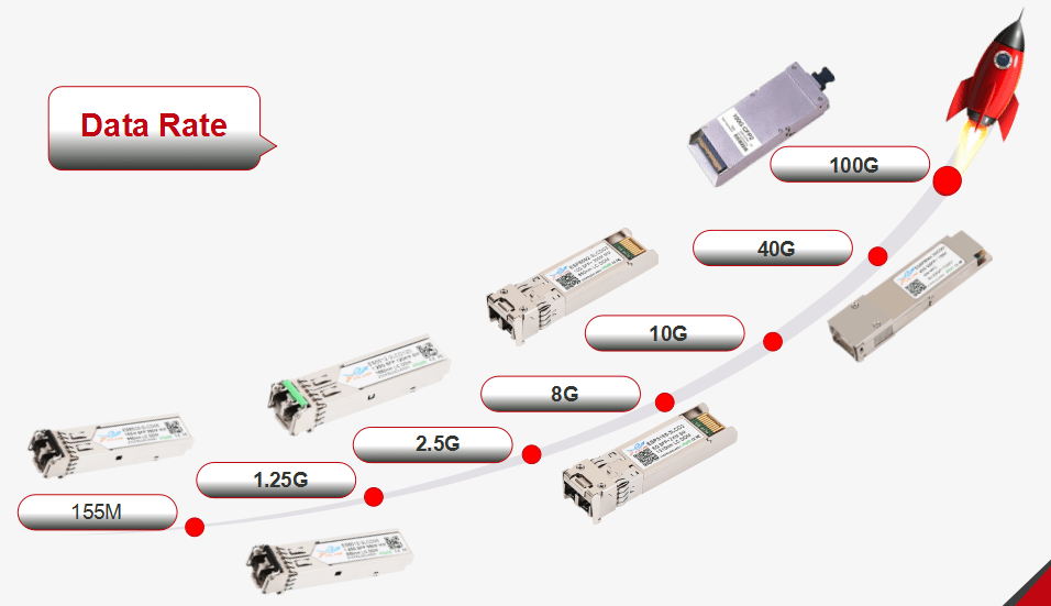
Optical Transceiver Module Data Rate
Transmission distance
The common optical modules are divided into short distance (300M-2KM), middle distance (10KM-40KM), long distance (>40km), The farther the transmission distance, the higher the technical and technological requirements of the optical module.
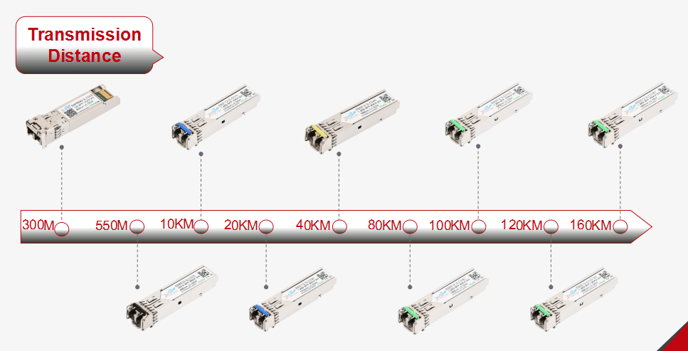
Optical Transceiver Module Transmission Distance
Modules Compatibility
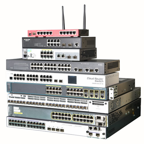
Modules Compatibility
When purchasing optical modules, need to confirm whether it can be compatible with your devices. Common switch brands like CISCO, HUAWEI, H3C, Juniper, D-link, HP, IBM, dell, Mikrotik etc., modules need to be tested compatibility before shipment. Before purchasing, it is best to confirm that it can be perfectly compatible with the corresponding brand switch.
Select the original one or compatible one according to the budget situation
The original module is reliable but the price is too high, compatible module is cost-effective, comparable to the original module. Different users need to make specific choices according to the budget.

Reviews
There are no reviews yet.