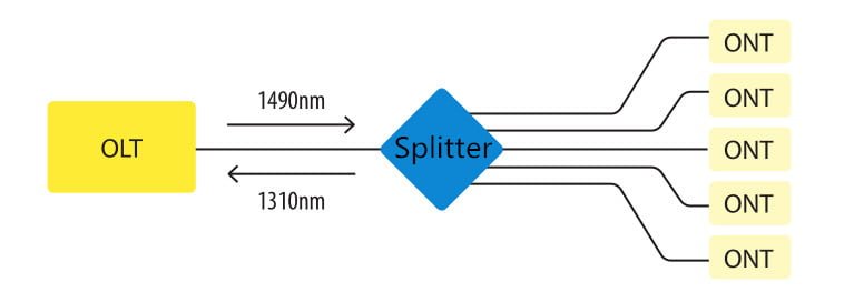
Optical splitters play an important role in FTTH PON networks where a single optical input is split into multiple output, thus allowing a single PON interface to be shared among many subscribers. The optical splitters have no active electronics and don’t require any power to operate. They are typically installed in each optical network between the PON OLT (optical line terminal) and ONTs (optical network terminals) that the OLT serves. Generally, two kinds of fiber optic splitters are popular, which are FBT splitters and PLC splitters. The differences between the two have been stated in another article—FBT Splitters vs. PLC Splitters: What Are the Differences? So it is unnecessary to go into the details here. Besides these, what other information do you know about optical splitters? Keep reading this article, you may get more about it.
Split Ratios
There are a multitude of split ratios available. The most common splitters deployed in a PON system is a uniform power splitter with a 1:N or 2:N splitter ratio, where N is the number of output ports. The optical input power is distributed uniformly across all output ports. Splitters with non-uniform power distribution is also available but such splitters are usually custom made and command a premium. Generally, the 1:N splitters are deployed in star networks, while 2:N splitters are deployed in ring networks to provide physical network redundancy.

The use of optical splitters in PON allows the service provider to conserve fibers in the backbone, essentially using one fiber to feed as many as 64 end users. A typical split ratio in a PON application is 1:32, meaning one incoming fiber split into 32 outputs. And the qualified fiber optic signal can be transmitted over 20 km. If the distance between the OLT and ONT is small (in 5 km), you can consider about 1:64. With higher split ratios, the PON network has both advantages and disadvantages. Fiber optic splitters with higher split ratios can share the OLT optics and electronics costs as well as share feeder fiber costs and potential new install costs. In addition, larger splits allow more flexibility and fiber management at head end is simpler. At the same time, higher split ratio splitters reduce bandwidth per ONU (optical network unit). And there will be increased optics cost either at OLT or ONU or both to achieve large optical power budgets.Splitting Level
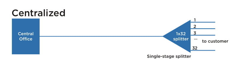
In the PON network, there are two common splitter configurations—centralized approach and cascaded approach.Centralized Approach
The centralized splitter approach typically uses a 1×32 splitter in an outside plant (OSP) enclosure, such as a fiber distribution terminal. The 1×32 splitter is directly connected via a single fiber to an OLT in the central office. On the other side of the splitter, 32 fibers are routed through distribution panels, splice ports or access point connectors to 32 customers’ homes, where it is connected to an ONT. Thus, the PON network connects one OLT port to 32 ONTs.
Cascaded Approach
The cascaded approach may use a 1×4 splitter residing in an outside plant enclosure. This is directly connected to an OLT port in the central office. Each of the four fibers leaving this stage 1 splitter is routed to an access terminal that houses a 1×8, stage 2 splitter. In this scenario, there would be a total of 32 fibers (4×8) reaching 32 homes. It is possible to have more than two splitting stages in a cascaded system, and the overall split ratio may vary (1×16=4×4, 1×32=4×8, 1×64=4x4x4).

Which to Choose?
It is important to understand both architectures in detail and weigh the trade-offs when deciding on the best approach. For most applications, the centralized approach is recommended.
First and foremost, the centralized approach maximizes the highest efficiency of expensive OLT cards. As each home in this approach is fiber-connected directly back to a central hub, there are no unused ports on the OLT card and 100% efficiency is achieved. This also allows a much wider physical distribution of the OLT ports—extremely important when initial “take rates” are projected to be low to moderate. Secondly, centralized approach is able to provide easy testing and troubleshooting access. The centralized 1×32 splitter with distribution ports enables OTDR trace development upstream to the central office and downstream to the access terminal. Also the connector ports available at the distribution hub enable qualification testing of the distribution cabling. Thirdly, loss will occur when splitters are cascaded together. The combined loss effect can reduce the distance a signal can travel, imposing distance limitations on fiber runs. The centralized splitter minimizes that signal loss by eliminating extra splices or connectors from the distribution network.
In general, the centralized architecture typically offers greater flexibility, lower operational costs and easier access for technicians, while the cascaded approach may yield a faster return-on-investment, lower first-in costs and lower fiber costs.Summary
This article has reviewed some information about the split ratios and splitting level of fiber optic splitters. It is very essential to make clear all these different configurations, or the network performance will be influenced if misunderstanding or misusing the optical splitters. Hope the information in this article can help when needed.