
QSFP+ 40G SR4 850nm 100m Optical Transceiver
$46.00
QSFP+ 40G SR4 850nm 100m Optical Transceiver Module CISCO, HUAWEI, H3C, Juniper, D-link, HP, IBM, dell, Mikrotik, Aruba,Quidway Compatible is a Four-Channel, Pluggable, Parallel, Fiber-Optic QSFP+ Transceiver for InfiniBand QDR/DDR/SDR,12G/10G/8G/4G/2G fiber channel, PCIe and SAS Applications.
What Is QSFP+ 40G SR4 850nm 100m Optical Transceiver Module?
QSFP+ 40G SR4 850nm 100m Optical Transceiver Module CISCO, HUAWEI, H3C, Juniper, D-link, HP, IBM, dell, Mikrotik, Aruba,Quidway Compatible is a Four-Channel, Pluggable, Parallel, Fiber-Optic QSFP+ Transceiver for InfiniBand QDR/DDR/SDR,12G/10G/8G/4G/2G fiber channel, PCIe and SAS Applications.The QSFP full-duplex optical module offers 4 independent transmit and receive channels, each capable of 11.3Gbps operation for an aggregate data rate of 45.2Gbps 100m using OM3 fiber. These modules are designed to operate over multimode fiber systems using 850nmVCSEL laser array. An optical fiber ribbon cable with an MPO/MTP connector can be plugged into the QSFP module receptacle.QSFP+ SR4 is one kind of parallel transceiver which provides increased port density and total system cost savings.
Product Features
- Four-channel full-duplex transceiver modules
- Transmission data rate up to 11.3Gbit/s per channel
- Up to 100m on OM3 Multimode Fiber (MMF) and 150m on OM4 MMF
- Low power consumption <1.5W
- Operating case temperature: 0 to 70℃
- 3.3V power supply voltage
- Hot Pluggable QSFP form factor
- MPO connector receptacle
- Built-in digital diagnostic function
Applications
- Proprietary High Speed Interconnections
- Infiniband QDR and DDR interconnects
- Data Center
QSFP+ 40G SR4 850nm 100m Optical Transceiver Module
Regulatory Compliance
| Feature | Standard | Performance |
| Electromagnetic Interference (EMI) | FCC Part 15 Class B EN 55022:2010, Class B | Compatible with standards |
| Electromagnetic susceptibility (EMS) | EN 55024:2010 | Compatible with standards |
| Laser Eye Safety | FDA 21CFR 1040.10 and 1040.11 EN60950, EN (IEC) 60825-1,2 | Compatible with Class I laser product |
Absolute Maximum Ratings
The operation in excess of any absolute maximum ratings might cause permanent damage to this module.
| Parameter | Symbol | Min | Max | Unit | Notes |
| Storage Temperature | TS | -40 | 85 | ℃ | |
| Operating Case Temperature | TOP | 0 | 70 | ℃ | |
| Power Supply Voltage | VCC | -0.3 | 3.6 | V | |
| Relative Humidity (non-condensation) | RH | 0 | 85 | % | |
| Input Voltage | Vin | -0.3 | Vcc+0.3 | V |
Recommended Operating Conditions and Power Supply Requirements
| Parameter | Symbol | Min | Typical | Max | Unit | Notes |
| Operating Case Temperature | TOP | 0 | 70 | ℃ | ||
| Power Supply Voltage | VCC | 3.135 | 3.3 | 3.465 | V | |
| Power Consumption | 1.5 | W | ||||
| Data Rate | DR | 10.3125 | 11.3 | Gbps | ||
| Data Speed Tolerance | ∆DR | -100 | +100 | ppm | ||
| Link Distance with OM3 fiber | D | 0 | 100 | m |
Electrical Characteristics
The following electrical characteristics are defined over the Recommended Operating Environment unless otherwise specified.
| Parameter | Test Point | Min | Typical | Max | Unit | Notes |
| Differential input impedance | Zin | 90 | 100 | 110 | ohm | |
| Differential Output impedance | Zout | 90 | 100 | 110 | ohm | |
| Differential input voltage amplitude | ΔVin | 300 | 1100 | mVp-p | ||
| Differential output voltage amplitude | ΔVout | 500 | 800 | mVp-p | ||
| Bit Error Rate | BR | E-12 | ||||
| Input Logic Level High | VIH | 2.0 | VCC | V | ||
| Input Logic Level Low | VIL | 0 | 0.8 | V | ||
| Output Logic Level High | VOH | VCC-0.5 | VCC | V | ||
| Output Logic Level Low | VOL | 0 | 0.4 | V |
Optical Characteristics
All parameters are specified under the recommended operating conditions with PRBS31 data pattern unless otherwise specified.
| Parameter | Symbol | Min | Typical | Max | Unit | Notes |
| Transmitter | ||||||
| Center Wavelength | λC | 840 | 860 | nm | 1 | |
| RMS Spectral Width | λrms | 0.65 | nm | 1 | ||
| Average Launch Power, each lane | PAVG | -7.6 | 2.3 | dBm | ||
| Optical Modulation Amplitude (OMA) | POMA | -5.6 | 0 | dBm | 1 | |
| Difference in Launch Power between any two lanes | Ptx,diff | 4.0 | dB | |||
| Launch Power in OMA minus Transmitter and Dispersion Penalty (TDP), each Lane | OMA-TDP | -6.5 | dB | 1 | ||
| Rise/Fall Time | Tr/Tf | 50 | ps | |||
| Extinction Ratio | ER | 3.5 | dB | |||
| Transmitter Eye Mask Margin | EMM | 10 | % | 2 | ||
| Average Launch Power OFF Transmitter, each Lane | Poff | -30 | dBm | |||
| Transmitter Eye Mask Definition {X1, X2, X3, Y1, Y2, Y3} | {0.23, 0.34, 0.43, 0.27, 0.35, 0.4} | |||||
| Receiver | ||||||
| Center Wavelength | λC | 840 | 850 | 860 | nm | |
| Damage Threshold | THd | 3.4 | dBm | |||
| Overload, each lane | OVL | 2.4 | dBm | |||
| Receiver Sensitivity in OMA, each Lane | SEN | -9.5 | dBm | |||
| Signal Loss Assert Threshold | LOSA | -30 | dBm | |||
| Signal Loss Deassert Threshold | LOSD | -12 | dBm | |||
| LOS Hysteresis | LOSH | 0.5 | 8 | dB | ||
| Optical Return Loss | ORL | -12 | dBm |
- Notes:Transmitter wavelength, RMS spectral width and power need to meet the OMA minus TDP specs to guarantee link performance.
- The eye diagram is tested with 1000 waveform.
Digital Diagnostic Functions
Digital diagnostics monitoring function is available on all RAYOPTEK QSFP+ SR4. A 2-wire serial interface provides user to contact with module. The structure of the memory is shown in Figure 3. The memory space is arranged into a lower, single page, address space of 128 bytes and multiple upper address space pages. This structure permits timely access to addresses in the lower page, such as Interrupt Flags and Monitors. Less time critical time entries, such as serial ID information and threshold settings, are available with the Page Select function. The interface address used is A0xh and is mainly used for time critical data like interrupt handling in order to enable a one-time-read for all data related to an interrupt situation. After an interrupt, IntL, has been asserted, the host can read out the flag field to determine the affected channel and type of flag.
| Parameter | Symbol | Min | Max | Unit | Notes |
| Temperature monitor absolute error | DMI_Temp | -3 | +3 | ℃ | Over operating temperature range |
| Supply voltage monitor absolute error | DMI_VCC | -0.1 | +0.1 | V | Over full operating range |
| Channel RX power monitor absolute error | DMI_RX | -3 | +3 | dB | 1 |
| Channel Bias current monitor | DMI_Ibias | -10% | +10% | mA |
What is an (Fiber) Optical Transceiver?
An Optical transceiver module is the core part of optical communication devices. It uses fiber optical technology to send and receive data through completing the process of optical signal – electrical signal / electrical signal – optical signal conversion. An optical transceiver module consists of two parts: the receiving part and the transmitting part. The receiving part realizes the photo-electric conversion, and the transmitting part realizes the electro-optical conversion.
Usually, one end of the transceiver will be connected to a cable and the opposite end of will have a special connector for fitting it into specific models of enterprise-grade Ethernet switches, routers or network interface cards
How to Classify Optical Transceivers?
In order to meet a variety of needs of transmission, the manufacturers launched a variety of categories of optical modules. Below are some common methods to classify them.
1)Sort by Rate
400GE optical transceiver module,
200GE optical transceiver module,
100GE optical transceiver module,
40GE optical transceiver module,
25GE optical transceiver module,
10GE optical transceiver module and etc.
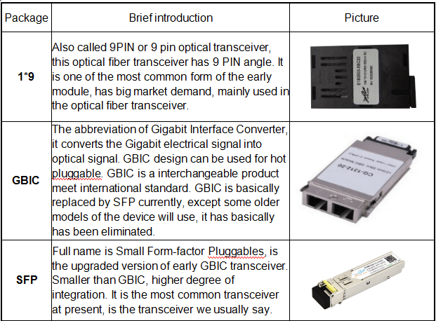
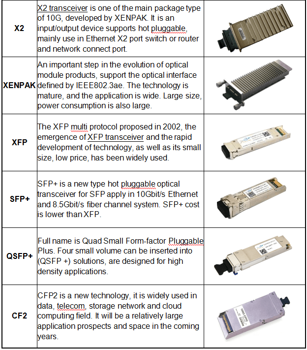
2)Sort by Package
The higher the transmission rate of the optical transceiver, the more complex the structure. In order to meet the needs of different structures, a variety of packaging types of optical transceiver modules were designed. For example, XFP, SFP, SFP+ for 10G transceivers, QSFP+ for 40G transceivers, CFP4, CFP2 and QSFP28 for 100G transceivers, as well as the latest OSFP and QSFP-DD for 400G transceivers.
- XFP (10GB Small Form-factor Pluggable) optical module: “X” is the abbreviation of Roman numerals 10, all XFP modules are 10G optical module. The XFP optical module supports LC fiber optic connectors and supports hot plugging. Compared to SFP+ and SFP optical modules, XFP optical modules are larger and longer.
- SFP (Small Form-factor Pluggable) optical module: smaller than XFP, SFP optical modules support LC fiber optic connectors, hot plugging.
- SFP+ (Small Form-factor Pluggable Plus) optical module: SFP+ refers to the increased rate of SFP module, sensitive to EMI.
- QSFP+ (Quad Small Form-factor Pluggable Plus) optical module: four-channel small hot plugging optical module. The QSFP + optical module supports MPO fiber connectors, which are larger in size than SFP + optical modules.
- CFP (Centum Form-factor Pluggable) optical module: length × width × height of CFP is defined as 144.75mm × 82mm × 13.6mm, high-speed, hot plugging and supporting for data communications and telecommunications applications.
- QSFP28 optical module: the interface package size of QSFP28 is the same with QSFP+, which is mainly used in Data Center application.
- OSFP (Octal Small Form Factor Pluggable) optical module: the OSFP is a new pluggable form factor with eight high speed electrical lanes that will initially support 400 Gbps (8x50G). It is slightly wider and deeper than the QSFP but it still supports 32 OSFP ports per 1U front panel, enabling 12.8 Tbps per 1U.
- QSFP-DD (Quad Small Form Factor Pluggable Double Density) optical module: QSFP-DD is a new module and cage/connector system similar to current QSFP, but with an additional row of contacts providing for an eight lane electrical interface. It is being developed by the QSFP-DD MSA as a key part of the industry’s effort to enable high-speed solutions.
Optical Transceiver Module classification
Optical Transceiver Module classification
3)Sort by Physical Layer Standard
In order to allow the data to be transmitted in different conditions and applications, optical communication industry defined of a variety of different physical layer standards, which resulting in a variety of optical transceiver modules supporting different standards.
For example, IEEE and MSA industry alliances have set several criteria for the 100G QSFP28 optical modules, like SR4, LR4, ER4, PSM4, CWDM4 and etc.
4)Sort by Pattern
As we all know, fiber can be divided into single-mode fiber and multi-mode fiber. In order to use different type of fiber, we also classify optical transceiver modules into single-mode optical modules and multi-mode optical modules.
Single-mode optical module is used to match single-mode fiber with better transmission capacity, which is suitable for long-distance transmission.
Multi-mode optical module is used to match multi-mode fiber. Multimode fiber has the defect of mode dispersion, its transmission performance is poorer than single-mode fiber. However, with better cost performance, they are popular in smaller capacity, short distance transmission.
How to choose the right optical module?
With the rapid development of information technology, the application of optical communication has become more and more popular. With the advantages of large capacity and high-speed transmission, Fiber Optic Transceiver Modules is playing a more and more important role. Where there is fiber, the optical module is needed, and the selection and purchase of the optical module has become the focus of the front-line engineering technicians or purchasing personnel.
There are many types of optical transceivers on the market, often dazzling. So, how to choose the most suitable module in many different speed, different packaging, different functions of the Optical Transceiver Module? We will give you some tips.
Choose the module based on your usage environment
How fast the speed of transmission you need? 155M, 1G, 10G or 100G? The higher transmission rate means higher cost investment. For example, the application environment of FTTH, it’s enough to use about 1G speed products for current bandwidth. It’s not necessary to choose 10G products with more money.
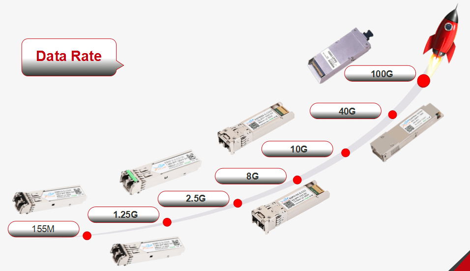
Optical Transceiver Module Data Rate
Transmission distance
The common optical modules are divided into short distance (300M-2KM), middle distance (10KM-40KM), long distance (>40km), The farther the transmission distance, the higher the technical and technological requirements of the optical module.
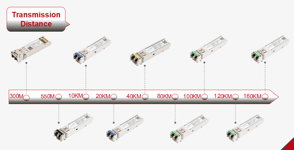
Optical Transceiver Module Transmission Distance
Modules Compatibility
Modules Compatibility
When purchasing optical modules, need to confirm whether it can be compatible with your devices. Common switch brands like CISCO, HUAWEI, H3C, Juniper, D-link, HP, IBM, dell, Mikrotik etc., modules need to be tested compatibility before shipment. Before purchasing, it is best to confirm that it can be perfectly compatible with the corresponding brand switch.
Select the original one or compatible one according to the budget situation
The original module is reliable but the price is too high, compatible module is cost-effective, comparable to the original module. Different users need to make specific choices according to the budget.
After-sale service
| Brand |
OEM |
|---|---|
| Model |
QSFP+ 40G SR4 850nm 100m |


Reviews
There are no reviews yet.