


3D Interference Testing Fiber Optic Connector Interferometer
$1.00
Fiber Optic Connector Interferometer The geometry of the end face or tip of fiber optic termini is a key factor for controlling the performance of the Fiber Optic connector. This geometry will determine which areas come into contact when two Fiber Optic connectors or termini are mated. This interference machine can generate an improvement guiding for polishing methodology In fiber . It including the polishing pressure,polishing time,polishing speed,polishing grain size and polishing pad hardness. The computer support data collection, data printing , network data transmission etc.
3D Interference Testing Fiber Optic Connector Interferometer This interference machine can generate an improvement guiding for polishing methodology. It including the polishing pressure,polishing time,polishing speed,polishing grain size and polishing pad hardness. The computer support data collection, data printing , network data transmission etc.
user can test almost all kinds of connecters. 2.5mm universal used to measure FC/PC.SC/PC.ST/PC, E2000/PC, DIN, FC/APC, SC/APC kinds of connectors, 1.25mm universal used to measure LC/PC, MU/PC, LC/APC kinds of connectors, and you don’t need to replace chucks and calibrate when you transfer between APC and PC connector mesurement, only turning “angle adjuster” to relative angle is ok, very convenient to operate.
measure the end face geometry of optical fiber connectors. It is used to measure standard fiber optic connectors such as SC/PC, SC/APC, FC/PC, FC/APC, ST, LC/PC, LC/APC, MU/PC connectors with diameter of 1.25mm or 2.5mm. Output parameters include Radius of Curvature (ROC), Fiber Height, Apex Offset, APC Angle and Key Angle, etc., which help to improve the end face polishing of fiber optic connectors, and lead to perfect transmission.
Importance of end face geometry
The geometry of the end face or tip of fiber optic termini is a key factor for controlling the performance of the Fiber Optic connector. This geometry will determine which areas come into contact when two Fiber Optic connectors or termini are mated. Measuring end face parameters such as the radius of curvature, the apex offset, and the fiber height during the polishing process provides both quality control and quality assurance. Controlling the end face geometry of a fiber optic termini provides the following benefits:
1. Helps guarantee optical performance
2. Minimizes Loss
3. Minimizes Back Reflection
4. Confirms Consistency for Quality Control of Polishing Process
5. Provides Assurance for Long Term Stability of the termini when exposed to the following: •Time •Temperature •Pressure •Vibration
Fiber optic testing machine 3D interference fiber malfunction microscope
Features
-Testing Time below 1.5 s
-Manual operating including X axis, Y axis movement, assessor, replacement for different types of connectors , focal length adjustment
Other operating is automatically
-The machine can generate an improvement guiding for polishing methodology.
It including the polishing pressure,polishing time,polishing speed,polishing grain size and polishing pad hardness.
-The computer support data collection, data printing , network data transmission etc.
Key Features and Benefits:
1、Test result maintains a high degree of consistency to all other brand equipment.
2、Fast response of measurement in 0.5 second.
3、Precise data processing, with high accuracy measurement results.
4、Novel robust algorithm, accurate results even with contaminated ferrule surface
5、High-precision and long life fiber clamp.
6、Automatically generate three-dimensional map, fitting map which directly reflect the details of the optical fiber connector;
7、Automatically generate test reports and test data in Excel format, which is easy to manage and print;
Specification:
Measure Item Measurement Range Repeatability Reproducibility
ROC(mm) 3~∞ ±0.03 ±0.05
Fiber Height(nm) -160~160 ±2.0 ±3.0
Apex-Offset(um) 0~500 ±1.0 ±2.0
APC Angle(deg) 7~9* ±0.01 ±0.02
APC Key Angle(deg) ±1 ±0.02 ±0.03
fiber interferometer,fiber interferometer stabilization,fiber interferometer system,fiber interferometer definition,interferometer fiber optics,interferometer fiber inspection,interferometer fiber sensor3d interference fibers,multi function fiber microscope,ferrule end face geometry,fiber end face geometry,fiber optic end face geometry,ferrule 3d model,ferrule 3d
Fiber Optic Connector End Face Geometry Measurement Techniques There are a number of instruments that can provide information on the end face geometry . Three common measuring devices are:
1. Stylus Profilometer
2. Atomic Force Microscope (AFM)
3. Interferometric microscope.

Auto Focus Fiber Connector Optical interferometer

Manual Focus Fiber Connector Optical interferometer

Software Interface in 2D interferometer mode
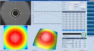
Software Interface in 3D interferometer mode

Customize Clamp Interferometer Fiber Optic Connectors
https://mefiberoptic.com/how-to-make-fiber-optic-patch-cord-and-pigtail-production-process/
https://mefiberoptic.com/fiber-jumpers-inspection-and-cleaning-methods/

Reviews
There are no reviews yet.