What Is Fiber Optic Coupler?

Fiber optic couplers are optical devices that connect three or more fiber ends, dividing one input between two or more outputs, or combining two or more inputs into one output. The device allows the transmission of light waves through multiple paths.
Passive and Active Couplers
Fiber optic couplers can either be passive or active devices.
Passive fiber optic couplers are said to be passive as no power is required for operation. They are simple fiber optic components that are used to redirect light waves. Passive couplers either use micro-lenses, graded-refractive-index (GRIN) rods and beam splitters, optical mixers, or splice and fuse the core of the optical fibers together.
Active fiber optic couplers require an external power source. They receive input signal(s), and then use a combination of fiber optic detectors, optical-to-electrical converters, and light sources to transmit fiber optic signals.
Types
Types of fiber optic couplers include splitters, combiners, X-couplers, trees, and stars, which all include single window, dual window, or wideband transmissions.
Fiber optic splitters take an optical signal and supply two outputs. They can further be described as either Y-couplers or T-couplers.
- Y-couplers have equal power distribution, meaning that the two output signal each receive half of the transmitted power.
- T-couplers have an uneven power distribution. The signal outputs still carrier the same signal, however the power of one output is greater than the second output.
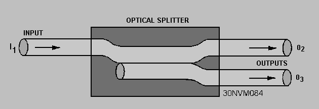
Image Credit: Integrated Publishing, Inc.
Fiber optic combiners receive two signals and provide a single output. The output signal is typically comprised of multiple wavelengths, due to the amount of interference that occurs when attempting to combine two signals that share the same wavelength.
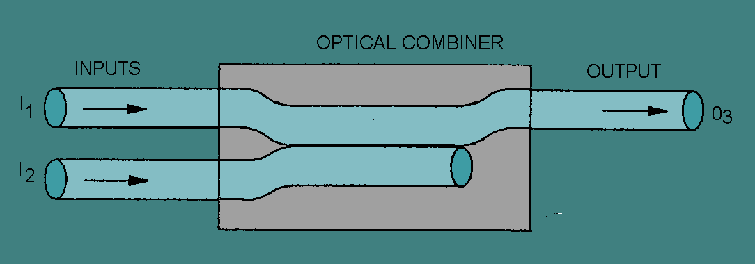
Image Credit: Integrated Publishing, Inc.
X-couplers carry out the function of a splitter and combiner in one package. They are a 2×2 coupler that combines the power of two signals and then divides the signal between two outputs.
Star couplers have M inputs and N outputs (MxN). They are used to distribute the power from all of the inputs to all outputs.

Image Credit: Fiber-Optics.Info
Tee couplers either have 1 input and M outputs (1xM) or N inputs and 1 output (Nx1).
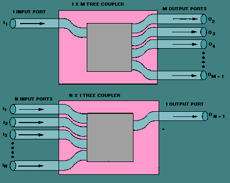
Image Credit: Integrated Publishing, Inc.
Mechanical Specifications
When specifying optical couplers you should consider the fiber optic cable, the coupler type, signal wavelength, number of inputs and outputs, as well as insertion loss, splitting ratio, and polarization dependent loss (PDL).
Fiber Optic Cable
Optical couplers support one of two cable types, single mode or multimode, which will allow either single or multiple paths for light to travel through the fiber respectively. Multimode cables limit the distance that the signal can travel as multiple paths of transmission cause modes of light to disperse limiting the transmission bandwidth. Multimode may be further classified as being step-index or graded-index. Graded-index fibers have improved operational characteristics; the refractive index gradient refracts separate modes of light propagation towards the central core, limiting the dispersion rate.
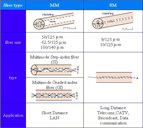
Image Credit: Cisco
Number of Inputs and Outputs
Optical couplers can be specified by the number of ports used for signal transmissions going in as well as out. The number and type of ports will be used to describe whether the device is in a splitter, combiner, X-coupler, star or tree coupler.
Coupler Type
Optical couplers should be selected based on the bandwidth or window. Regardless of the port types used, fiber optic couplers can be designed for single window, dual wavelength or wideband transmissions.
- Single window couplers are designed for a single wavelength with a narrow wavelength window.
- Dual wavelength couplers are designed for two wavelengths with a wide wavelength window for each.
- Wideband couplers are designed for a single wavelength with a wider wavelength window.
Wavelength
The electromagnetic spectrum encompasses all frequencies and wavelengths of light. The visible spectrum is a finite range of wavelengths that can be detected by the human eye. Fiber optic couplers transmit light waves from the far visible region, red (630nm), to the near infrared region (1700nm). Within this region specific frequency bands are used as to avoid absorption bands within the carrier medium, the optical fiber. Wavelength choices for fiber optic couplers include 633 nm, 830 nm, 1060 nm, 1300 nm, and 1550 nm.
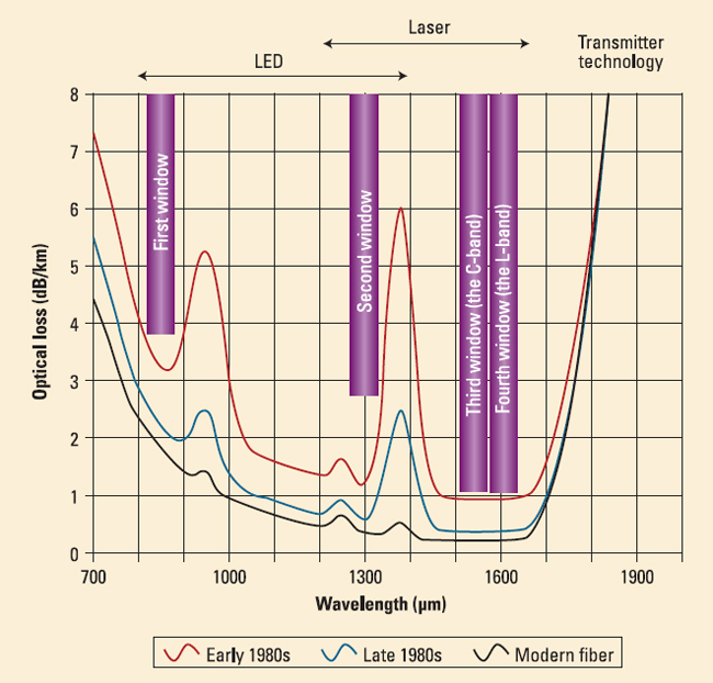
Image Credit: BroadcastEngineering
Insertion Loss
Fiber optic components disrupt signal transmissions as the continuous core of the optical fiber carrying the signal mates with the component in a manner that causes some amount of scattering and reflection of light waves. The degree to which the signal has been depleted is described as insertion loss, which is the undesired attenuation of the signal measured in decibels (dB).
Splitting Ratio
The splitting ratio is the distribution of power among the output fibers of a coupler; it is also referred to as the coupling ratio. A splitting ratio of 50/50 means that there is an equal distribution of optical power; a 60/40 ratio means 60% of the power is transmitted to a primary output and 40% to the secondary output.
Polarization Dependent Loss (PDL)
The polarization dependent losses are defined as the attenuation caused by polarization.
A fiber optic coupler is an indispensable part of the world of electrical devices. Without these no signals would be transmitted or converted from inputs to outputs. This is the reason these are so important thereby this article discussed about these, introduction, classification and benefits in detail.
Fiber Optic Coupler is an optical cog that is capable of connecting single or multiple fiber ends in order to permit the broadcast of light waves in manifold paths. This optical device is also capable of coalescing two or more inputs into a single output while dividing a single input into two or more outputs. In comparison to a connector or a splice, the signals may be even more attenuated by FOC i.e. Fiber Optic Couplers; this is due to the division of input signal amongst the output ports.
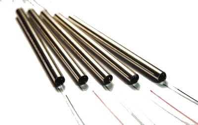
Types of Fiber Optic Coupler
Fiber Optic Couplers are broadly classified into two, the active or passive devices. For the operation of active fiber coupler an external power source is required, conversely no power is needed when it comes to operate the passive fiber optic couplers.
Fiber Optic Couplers can be of different types for instance X couplers, PM Fiber Couplers, combiners, stars, splitters and trees etc. Let’s discuss the function of each of the type of the Fiber Optic Couplers:
Combiners: This type of Fiber Optic Coupler combines two signals and yields single output.
Splitters: These supply multiple (two) outputs by using the single optical signal. The splitters can be categorized into T couplers and Y couplers, with the former having an irregular power distribution and latter with equal power allocation.
Tree Couplers: The Tree couplers execute both the functions of combiners as well as splitters in just one device. This categorization is typically based upon the number of inputs and outputs ports. These are either single input with a multi-output or multi-input with a single output.
PM Coupler: This stands for Polarization Maintaining Fiber Coupler. It is a device which either coalesces the luminosity signals from two PM fibers into a one PM fiber, or splits the light rays from the input PM fiber into multiple output PM fibers. Its applications include PM fiber interferometers, signal monitoring in its systems, and also power sharing in polarization sensitive systems etc.
Star Coupler: The role of star coupler is to distribute power from the inputs to the outputs.
Benefits of Fiber Optical Couplers
There are several benefits of using fiber optic couplers. Such as:
- Low excess loss,
- High reliability,
- High stability,
- Dual operating window,
- Low polarization dependent loss,
- High directivity and Stumpy insertion loss.
The listed benefits of Fiber Optical Couplers make them ideal for many applications for instance community antenna networks, optical communication systems and fiber-to-home technology etc.
