Why Should We Use Pulling Grip?
On many occasions, if the pulling distance is short (less than 3000 ft) and the pathway is straight enough, one can pull a fiber optic cable by hand without the help of any tools. Only when additional mechanical force or distance of long term is needed for a pull, the external pulling lines and pulling grips are needed.
Various types of pulling lines/ropes/tapes have been used successfully with optical cables. When pulling fiber optic cables, they are often referred to. And these pulling ropes are normally pulled through ducts to ensure a straight pulling path as shown below.
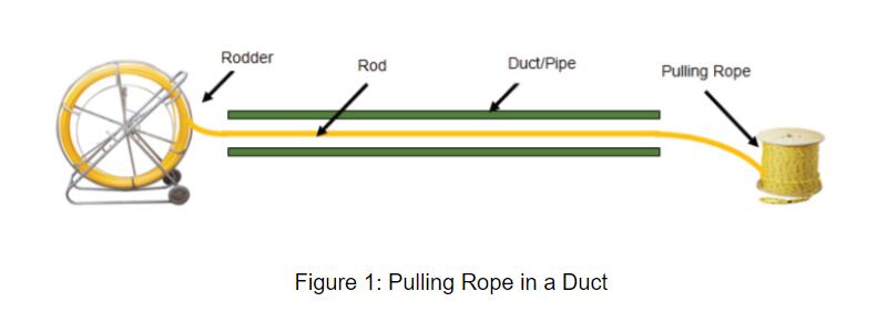
Since a pulling rope with a small diameter may cut the inner duct when being pulled, it is necessary to lubricate the pulling rope.
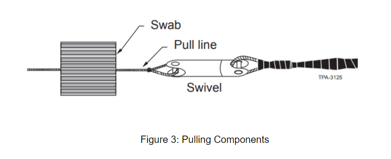
In addition, wire mesh pulling grip and breakaway swivel are recommended as well during cable pulls. External pulling grips (figure 2) are designed to lock into and tighten a fiber optic cable as a tensile load. The pulling end of the grip is a loop for attachment of the pulling tape or rope.

The pulling grips can provide effective coupling of pulling loads to the jacket, aramid yarn, and central member of fiber optic cables. The swivel installed between the pulling rope and the pulling grip makes sure a twist in the pulling rope is not translated to the fiber optic cable. And the swivel can be used to ensure that the maximum tension of the cable is not exceeded. During manual pulling, applied pulling tension higher than the cable tensile rating can damage the cable and negatively impact its lifetime. Featured with different tensile ratings, breakaway swivels will break if excess tension appears during cable pulling. For example, if cable rated tensile is 2700N and the breakaway swivel adopted has a fixed tensile strength of 2500N, when the cable pulling tension goes above 2500N , the swivel will break, making no impact on the fiber optic cable.
How to Install Pulling Grip Correctly?
This procedure provides instructions for installing a wire mesh pulling grip on multifiber tight-buffered fiber optic cables that are not connectorized. Examples of such cables include tight buffered cables, unitized cables and breakout cables.
Step 1: choose a pulling grip with a proper length.
The grip selection is based on the outside diameter of the fiber cable. Measure the cable diameter and determine the proper grip by locating the diameter in the table below.
| Cable Diameter Range in Inches (mm) | Mesh Length in Inches (mm) |
|---|---|
| 0.10 – 0.22 (3–6) | 10 (254) |
| 0.21 – 0.35 (5–9) | 14 (356) |
| 0.32 – 0.48 (8–12) | 19 (483) |
| 0.42 – 0.61 (11–15) | 21 (533) |
| 0.53 – 0.74 (13–19) | 23 (584) |
| 0.64 – 0.87 (16–12) | 25 (635) |
| 0.75 – 1.00 (19–25) | 28 (711) |
Step 2: inspect grip for damage
Check if the pulling grip has damages such as broken wires, bulges due to stress, rust, etc. If there is no damage, continue to the next step. Otherwise, you may need to change another grip.
Step 3: tighten the wires
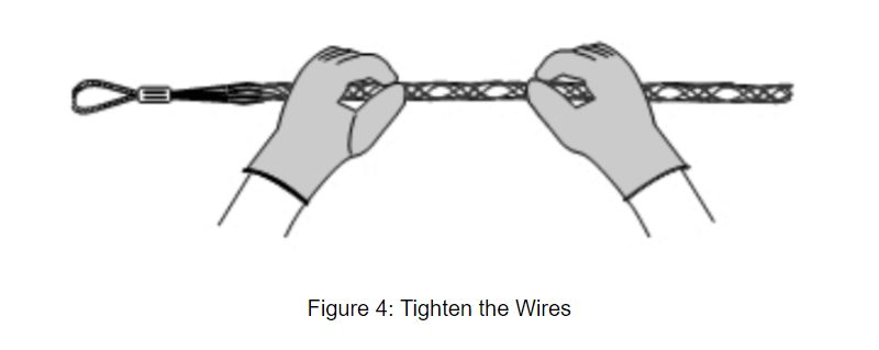
Grasp the pulling eye in one hand and smooth out the mesh with the other hand to tighten the wires. During the process, gloves are recommended to keep your hands from getting injured.
Step 4: trim the fiber cable
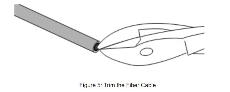
Trim the end of the cable with side cutters to remove any protruding tubes, yarn, strength members, or armor.
Step 5: mark and insert the cable into the grip
Mark the cable at half the length of the mesh area of the grip. Then, “walk” the cable through the grip until the mark is at least 3 inches (7.5 cm) past the end of the wire mesh.
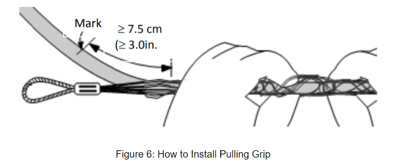
Step 6: remove the jacket up to the mark
Remove the jacket/sheath from the end (the trimming point) of the cable up to the mark.
Note: If the cables are non-unitized cables, first remove 6 inches (15 cm) of jacket and tape the cable components together with vinyl tape. Then, remove the remaining jacket.
Step 7: wrap the fiber core
Wrap one layer of the friction tape over the entire length of the fiber core exposed because of jacket removal. Please be noted that the friction tape can not be replaced by black electrical tape, whose slick outer surface could affect the performance of the pulling grip.
Step 8: wrap/encircle the jacket-removed cable core
Continue to “walk” the grip to encircle the friction tape-covered cable core. Smooth the mesh back over the cable core and tighten the mesh against it.
Step 9: tighten the whole cable and mesh together
Wrap vinyl tape from the other side of the cable (the side with cable jacket) to the top of the grip. The starting point of the cable wrapping is at least 1 inch (2.5 cm) below the mesh.
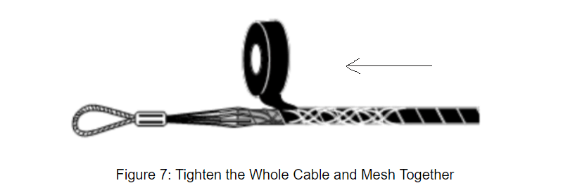
Step 10: Finish the pulling grip installation
Connect the pulling eye/pulling grip to the appropriate ball-bearing swivel and pulling tape/line to finish grip installation.
After installing the pulling grip correctly, one can begin pulling the cable. To ensure not exceeding the maximum tensile force of the fiber optic cable, tension-monitoring equipment is important. Normally, a winch with a calibrated maximum tension is an acceptable procedure for the monitor. A dynamometer or in-line tensiometer may also be used to monitor tension in the pulling line near the winch. Last but not least, cut 36 inches (91 cm)of the fiber optic cable behind the pulling grip and place a protective cap over the end of the cable to prevent water or dirt intrusion after finishing the pulling.
