Mostly, all optical amplifiers are used in optical communication. Generally, Brillouin type amplifier is not used in optical communication. For a particular use, the decision has to be made about which amplifier to be used. The EDFA amplifier is used in-line amplifier on account of its compatibility. On the other hand, Raman Fiber Amplifier (RFA) will be a very good power amplifier because of its high saturation.
EDFAs and conventional lasers, achieve gain by pumping atoms into a high energy state. This allows the atoms to release their energy when a photon of a suitable wavelength passes nearby. RFAs utilize Stimulated Raman Scattering (SRS) to create optical gain. Because SRS robs energy from shorter wavelengths and feeds it to longer wavelengths, high channel count DWDM systems initially avoided this technique.
A RFA amplifier consists of little more than a high-power pump laser, usually called a Raman laser, and a WDM or directional coupler. The optical amplification occurs in the transmission fiber itself, distributed along the transmission path. With amplification up to 10 dB, RFAs provide a wide gain bandwidth (up to 100 nm), allowing them to operate using any installed optical fiber (single mode optical fiber, TrueWave, etc.). By boosting the optical signal in transit, RFAs reduce the effective span loss and improve noise performance.
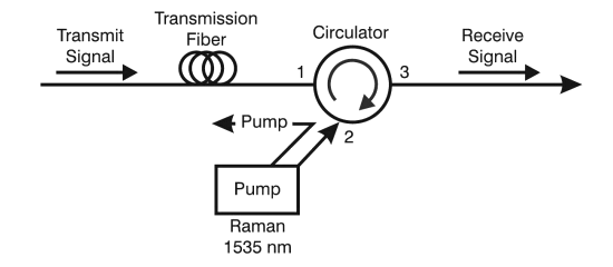
Combined with EDFAs, RFAs create a wide gain-flattened optical bandwidth. The figure belwo shows the topology of a typical RFA. The pump laser and optical circulator comprise the two key elements of the RFA amplifier. In this case, the pump laser has a wavelength of 1535 nm. The optical circulator provides a convenient means of injecting light backwards into the transmission path with minimal optical loss.
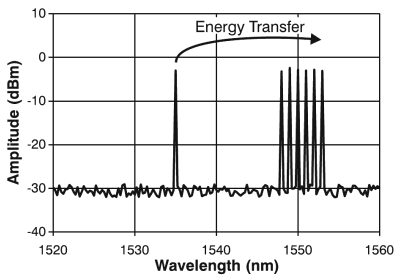
Here are the figures which show the optical spectrum of a forward-pumped RFA amplifier and the received signal after the same length of fiber used in the SRS example. The signal gets injected by the 1535 nm pump laser at the transmit end rather than the receive end. Generally, the amplitude of the pump laser exceeds that of the data signals.
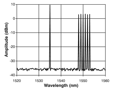
With a significant decrease in the amplitude of the pump laser, the amplitude of the six data signals has increased, giving all six signals roughly equal amplitudes. In this case, the SRS effect robbed a great deal of energy from the 1535 nm pump laser signal and redistributed that energy to the six data signals.