Why Fiber Optic Cables Need Lightning Protection Systems?
Lightning is an electrical discharge within clouds either from cloud to cloud or from cloud to the earth. It has great impacts on communication stations and other signal circuits. For example, it will not only affect all DWDM fiber channels in short bursts, but also affect transmission directions simultaneously according to numerous researches. It will even cause a fire when there are high current lightning discharges. Although the signals in fiber cables are optical signals, most of the outdoor optical cables using reinforced cores or armored optical cables are easy to get damaged under lightning because of the metal protective layer inside the cable. Therefore, it is important to build a lightning protection system for fiber optic cables.

How to Protect Fiber Optic Cable From Lightning?
The major purpose of lightning protection systems is to conduct the high current lightning discharges safely into the Earth/ground. There are two main lightning protection grounding solutions in fiber networks, namely intermediate grounding and terminal grounding. These solutions use two ways of grounding for optical cable links both in domestic and foreign standards. One is to make full electrical connections and grounding in the machine room, the other is to insulate the metal parts of each optical cable at the joints and make cables entering the equipment room grounded as well.
Intermediate Grounding Solutions
The intermediate grounding solutions are mainly designed for direct burial fiber cables and aerial fiber cables. Direct burial fiber cables are laid with lightning protection wires according to the soil resistivity, and the aerial fiber cables are grounded with grounding poles and suspension wires.
Grounding Solutions for Direct Burial Fiber Cables
When the lightning strikes the ground near the direct burial fiber cables, the electric potential of the strike point rises rapidly and the soil is ionized to generate an arc and become a conductor, making the optical cable conductive. Underground places like wet areas or with conductive deposits are vulnerable to lightning strikes. These places should be laid with lightning protection wires according to the soil resistivity range listed below:

Grounding Solutions for Aerial Fiber Cables
The isolated buildings on the plains, wilderness or on the top of the hill are prone to lightning strikes. The aerial fiber cables in these places are better grounded with aerial optic fiber cables. Grounding measures for aerial optic fiber cables are divided into pole grounding and suspension wire grounding.
In pole groundings, lightning protection wires are needed every 250 meters between the poles. If the length of the poles exceeds 12 meters or the angle depth in angular poles is greater than one meter, lightning protection wire is a necessity as well. Please be noted that the lightning protection wires should be installed with a fixed gap distance of 50 mm when the pole is set at the junction of high voltage (over 10 kv) power transmission lines.
What’s more, the underground extension of the lightning protection wires should be buried below 700 mm on the ground. The extension length and resistance of the wires should follow the requirements as the table shown below:
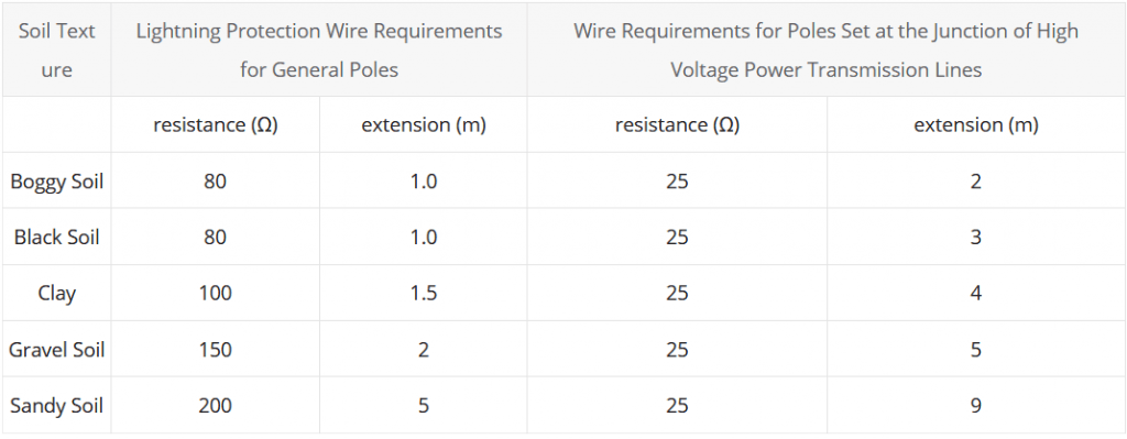
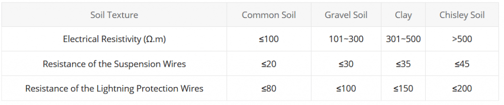
In suspension wire groundings, the suspension wires are grounded through lightning protection wires in pole groundings every 300-500 meters and electrical insulators will be added every 1 km or so for electrical disconnection. The resistance value of the suspension wires and lightning protection wires shall be in accordance with the table below:
Terminal Grounding Solutions
In the terminal grounding solutions, the optical cable terminal equipment should all be grounded. These equipment include optical distribution frames (ODFs), fiber optic cabinets, fiber distribution boxes, fiber terminal boxes, etc. Their grounding solutions are nearly the same. Here is an example of terminal grounding using an ODF.

In an optical cable distribution frame, the metal component of the optical cable should be connected to the high-voltage protective grounding device with a copper ground wire, whose cross-sectional area is not less than 6 square millimeters. Then, a multi-strand copper cable, whose cross-sectional area is not less than 35 square millimeters, should be used to connect the grounding device and extend to the existing grounding system in the machine room. There is a subtle difference when the optical cable line enters transfer devices like fiber distribution boxes. The cross-sectional area of the copper cable should be not less than 16 square millimeters rather than 35 square millimeters when extending to the existing grounding system.