Fiber optic cable, which is lighter, smaller and more flexible than copper, can transmit signals with faster speed over longer distance. However, many factors can influence the performance of fiber optic transmission. Losses in optical fiber are negligible issues among them, and it has been a top priority for every engineer to work with and figure out solutions for.
Different Types of Losses in Optical Fiber
The various losses in optical fiber are due to either intrinsic or extrinsic factors. Fiber attenuation, which is also called signal loss or fiber loss, is the consequence of the intrinsic properties of an optical fiber (multimode and single mode fiber). Apart from the intrinsic fiber losses, there are some other types of losses in the optical fiber that contribute to the link loss, such as splicing, patch connections, bending, etc.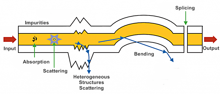
Figure 1: Different types of losses in optical fiber.
Intrinsic Optical Fiber Losses
Absorption losses in optical fiber are the major cause of optical fiber losses during the transmission. When the photon interacts with the components of the glass, an electron or metal ions, the light power is absorbed and transferred into other forms of energy like heat, due to molecular resonance and wavelength impurities.
Dispersion losses are the results of the distortion of optical signal when traveling along the fiber. Dispersion losses in optical fiber can be intermodal or intramodal. Intermodal dispersion is the pulse broadening due to the propagation delay differences between modes in multimode fiber. Intramoal dispersion is the pulse spreading in single mode fiber, because the refractive index or the propagation constant varies with wavelength.
Scattering losses in optical fiber are due to microscopic variations in the material density, compositional fluctuations, structural inhomogeneities and manufacturing defects.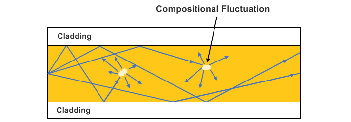
Figure 2: Light scattering due to compositional fluctuations.
The above three factors are the intrinsic attenuation losses in optical fiber. According to EIA/TIA-568 standards, the fiber losses for different fiber types are as following:
| Fiber Type | Wavelength | Fiber Loss |
|---|---|---|
| Multimode 50/125 µm (OM2/OM3/OM4) | 850 nm | 3.5 dB/km |
| Multimode 62.5/125 µm (OM1) | 850 nm | 3.5 dB/km |
| Single-mode 9 µm | 1310 nm | 0.4 dB/km |
| Single-mode 9 µm | 1550 nm | 0.3 dB/km |
Extrinsic Optical Fiber Losses
Fiber optic splicing is another type of loss in optical fiber. By joining two optical fibers end-to-end, splicing aims to ensure that the light passing through it is almost as strong as the virgin fiber itself. But no matter how good the splicing is, the splicing loss is inevitable. Fusion splicing losses of multimode fiber are 0.1-0.5 dB, 0.3 dB being a good average value. For single mode fiber, the fusion splicing loss typically can be less than 0.05 dB.
Connector losses or insertion losses in optical fiber, are the losses of light power resulting from the insertion of a device in a transmission line or optical fiber. Multimode connectors will have losses of 0.2-0.5 dB (0.3 typical). Factory made single mode connectors will have losses of 0.1-0.2 dB and field terminated single mode connectors may have losses as high as 0.5-1.0 dB (0.75 dB, TIA-568 max acceptable).
Bending is the common problem that can cause optical fiber losses generated by improper fiber optic handling. There are two basic types. One is micro bending, and the other one is macro bending (shown in the picture below). Macro bending refers to a large bend in the fiber (with more than a 2mm radius).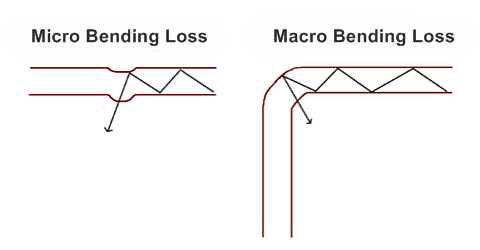
Figure 3: Bending losses in optical fiber.
Optical Fiber Losses Measurement
When measuring the total losses in optical fiber, also used to calculate the “link budget”, the above-mentioned types of losses should all be considered. Besides, the light power budget margin (due to the aging of the fiber, incidental bend and twisting, etc.) is also important. Most system designer will add a loss budget margin of 3-10 dB . Of course this rule is irrelevant if the power budget is ~2 dB like some of the 10G multimode links. So the calculation of losses in optical fiber should be:
Link Budget = [fiber length (km) * fiber attenuation per km] + [splice loss * # of splices]+[connector loss * # of connectors] + [safety margin]
Here’s an example of a typical 850nm 2km multimode link with 5 connections (2 connectors at each end and 3 connections at patch panels in the link) and one splice in the middle. The loss budget margin is 5 dB. So the total optical fiber loss of this link is:
[2 km*3.5 dB/km] + [1*0.3 dB] + [5*0.3 dB] + 5 dB = 12.3 dB.How to Reduce Losses in Optical Fiber
In order to ensure the output power can be within the sensitivity of the receiver and leave enough margin for the performance degradation with the time, it is an essential issue to reduce the losses in optical fiber. Here are some common approaches in fiber link design and installation. Make sure to adapt the high-quality cables with same properties as much as possible. Choose qualified connectors as much as possible. Make sure that the insertion loss should be lower than 0.3dB and the additional loss should be lower than 0.2dB. Try to use the entire disc to configure (single disc more than 500 meters) in order to minimize the number of joints. During splicing, strictly follow the processing and environment requirements. The connecting joints must have excellent patch and closed coupling so that can prevent the light leakage. Make sure of the cleanliness of the connectors. Choose the best route and methods to lay the fiber cables during design the construction. Select and form a qualified construction team to guarantee the quality of the construction. Strengthen the protection work, especially lightning protection, electrical protection, anti-corrosion and anti mechanical damage. Use high quality heat-shrinkable tube. Use high quality heat-shrinkable tube.
IEC Standard for Different Insertion Loss of Fiber Patch Cables
IEC standards introduce the connector performance requirement for each grade of fiber patch cable. These standards guide end users and manufacturers to make best use of optical cables within the regulations. According to IEC 61753-1 Attenuation of Random Mated Connectors, the insertion loss of mated connectors can be categorized in 4 different grades. The following shows the performance characteristics of each grade connector:
| Grade | Max Insertion Loss | Mean Insertion Loss |
|---|---|---|
| IEC Random Mating Grade A | ≤0.15 dB | ≤0.07 dB |
| IEC Random Mating Grade B | ≤0.25 | ≤0.12 dB |
| IEC Random Mating Grade C | ≤0.50 dB | ≤0.25 dB |
| IEC Random Mating Grade D | ≤1.0 dB | ≤0.50 dB |
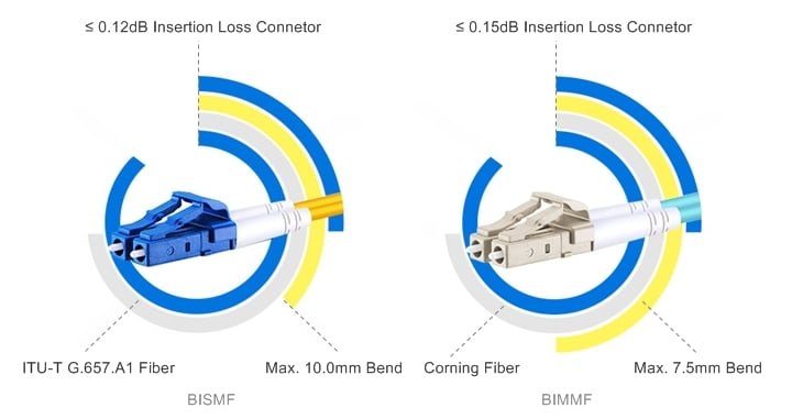
Ultra Low Loss BIF Fiber Cable
When it comes to high-quality fiber patch cables that help in reducing losses in optical fiber, WE offers bend insensitive fiber (BIF) patch cables with ultra low insertion loss (IL) and bend radius, ensuring high performance of data transmission. Our bend insensitive single mode fiber (BISMF) patch cables are made of G.657.A1 standard fiber from Corning and connectors with a 0.12dB typical IL, owning a minimum bend radius of 10.0 mm. Insertion loss of these BISMF patch cable connectors is rated as grade B in Random Mating, which is rather high-performance specified by IEC 61753-1. And the bend insensitive multimode fiber (BIMMF) patch cables have a 0.15dB typical IL, with a minimum bend radius of 7.5 mm. Our BIMMF cables can be spliced or connected to conventional multimode fiber cables without any problem.